My girlfriend bought herself a Singer Brilliance 6180 sewing machine from Lidl last Christmas. This turned out to have been a big mistake; it’s one of the least reliable and most annoying sewing machines to use in the world. Having replaced it with a vintage machine from the 1980s, she gave up on the 6180, and passed it to me to play with. Of course, I did the obvious thing and dismantled it immediately to see if any of the problems were electronics-related rather than purely mechanical issues. As it turns out, there are some problems in both categories, but there’s a lot of potential for hacking this machine.
Mechanics

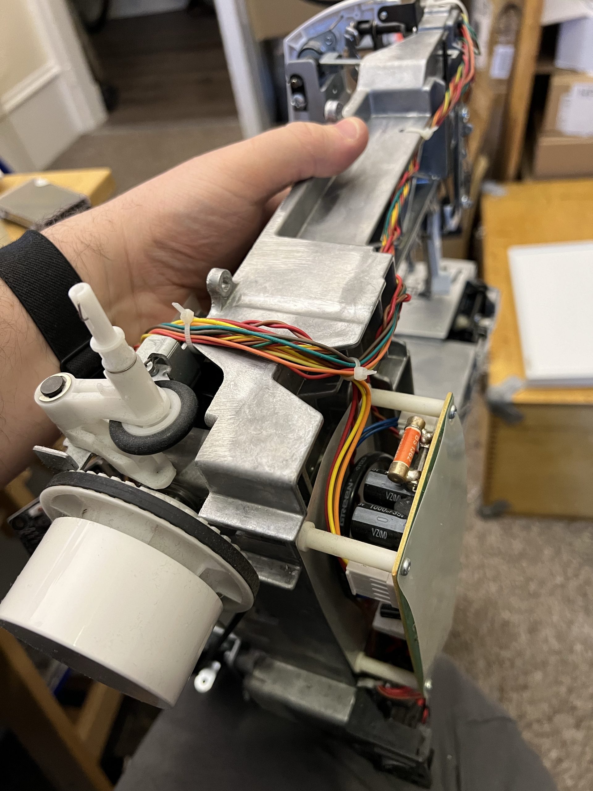
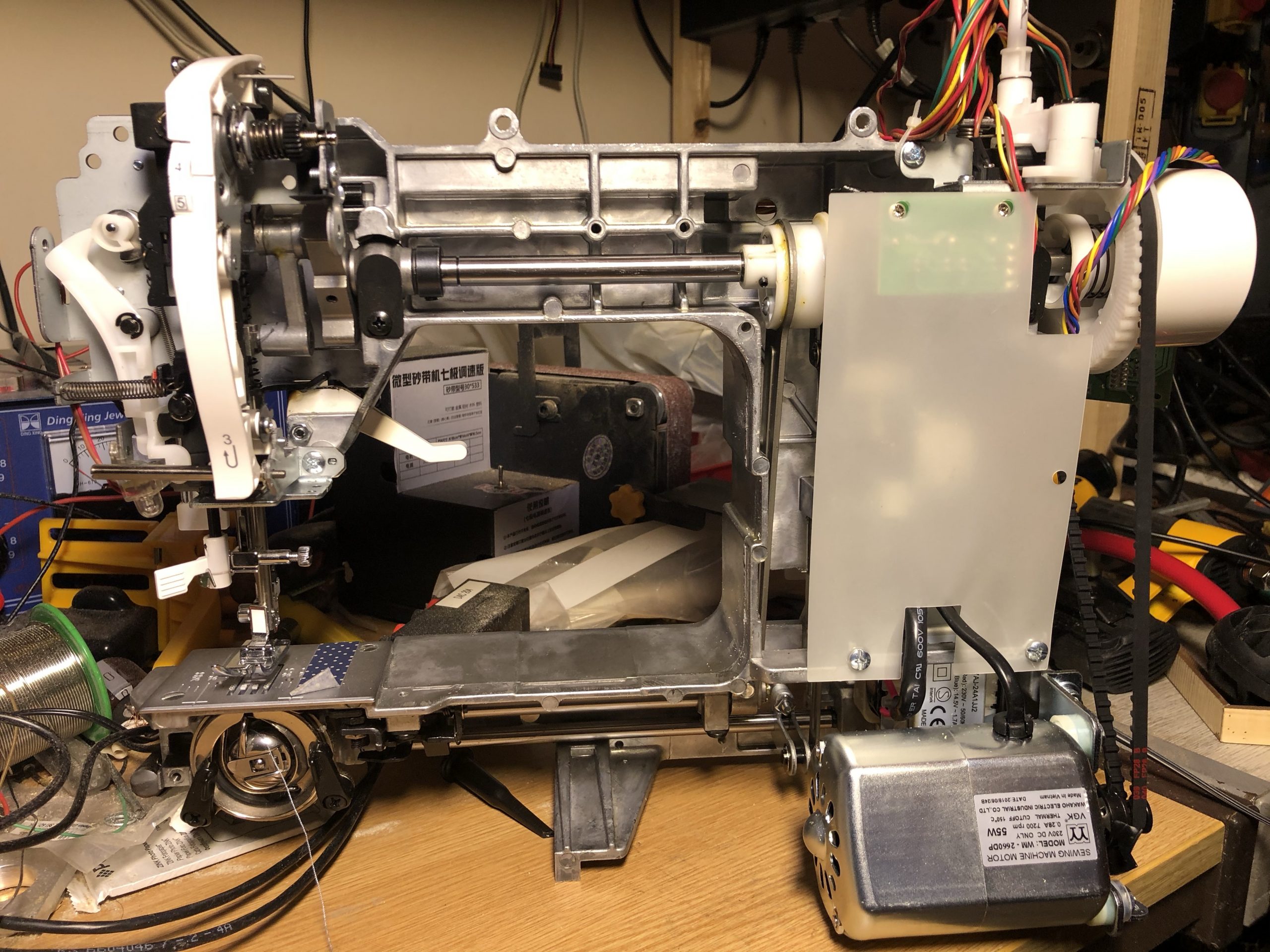
The machine itself is based around a die-cast chassis, with a very basic and conventional sewing machine mechanism with a front-loading bobbin. The mechanical parts of this machine could be considered to be a slightly tweaked straight-stitch only sewing machine, and indeed if you could power the motor without the normal control board, it would function perfectly well like this with no electronics involved. The electronic parts exist primarily to control two small stepper motors; one which moves the needle left-to-right (X-axis, essentially), and one which changes the stitch direction and length by adjusting the position of a lever that controls the feed dogs. Of course, to time movement of these parts correctly, there are also some feedback sensors, and a limited amount of control of the main motor.
The biggest problem – the X axis
This machine has a few problems, but the most severe by far is the tendency for the needle to fall out of alignment left-to-right and break. This can happen whenever the fabric presents any resistance to the movement of the needle, or whenever the machine is running quickly.
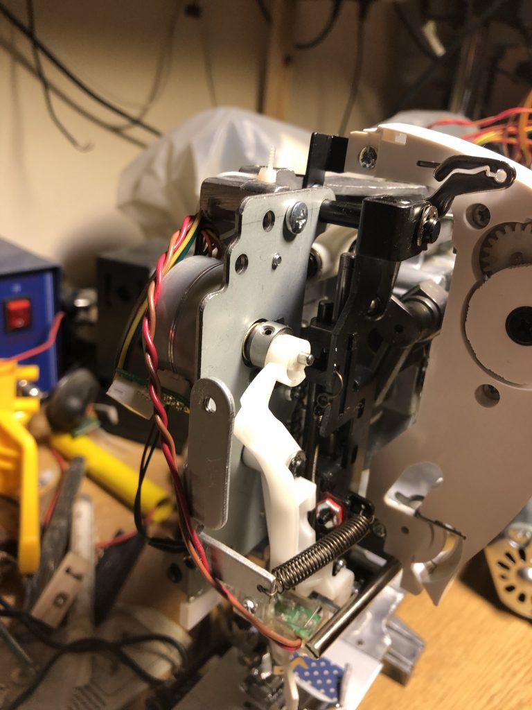
The underlying problem here is that the left-to-right movement of the needle is controlled by lever pushing on a cam attached to a stepper motor with a fairly weak spring to keep it in contact. Any sideways pressure away from the cam – or even the momentum of the assembly – can cause the needle to be out of position, and this quickly leads to needle breakage or jams. In addition, there’s no feedback or zeroing mechanism on this axis – it relies simply on hitting the endstop during startup or the first time the needle is in the “up” position (more on that later). It appears that there’s some provision in the electronics for a limit switch, but it’s not used on this model.
Y-axis
The Y-axis, by comparison, is better engineered. The Y-axis motor turns a gear, which in turn moves a toothed cam, which is attached to a lever that shifts the relative timing of the feed dogs. A proper limit switch is present, and during startup or the first time the main shaft passes a safe point (6 index slots past the start of the unsafe period), this motor will zero itself and then move to the appropriate position for sewing. A mechanical stop identical to that on the X-axis also exists; this suggests that the two axes may originally have have the same setup, but that the X-axis was simplified as a cost reduction.
Speed control
The motor in this machine is not controlled directly by the user. Instead, the electronics generate a PWM signal to select the appropriate motor speed. A relay is also present as a motor enable/disable. It’s not clear why this is required; perhaps it’s simply a safety feature to ensure that the motor is disconnected from power whenever it’s not intentionally being controlled by the processor. The pedal is a simple 20K variable resistor, wired as an input to the main processor. A second speed control input also exists, which is not used on this model, but which sets a speed limit on other machines based on the same chassis and electronics (e.g. Stylist 7258).
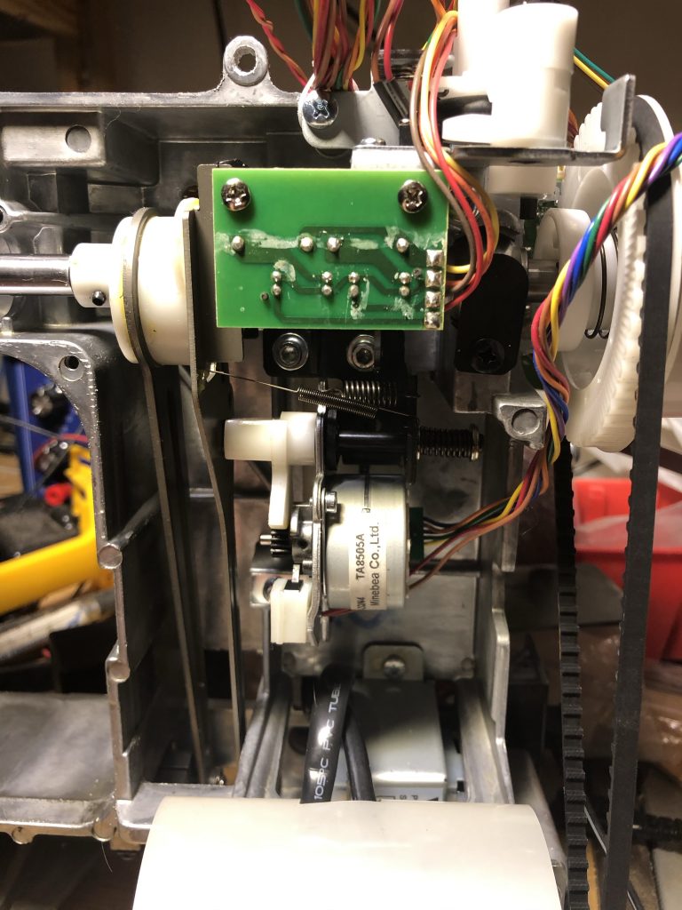
The main shaft has two slotted opto sensors connected to it. One is connected to a simple slotted wheel, to provide position feedback on the shaft. The other one detects a disk which provides a needle up/down signal; the disk blocks the sensor whenever the needle is down far enough for it to be unsafe to move it left to right.
Electronics
There are two large PCBs in the Brilliance; one power supply input board, which also contains the motor speed controller and switching relay, and one with the main processor, keypad, and stepper drive electronics. The power supply board provides only a 20V supply to the main control board, and accepts two control signals; one for the motor relay, and one for the PWM control. These two signals are pulled up to 12V by the power supply board, and are active-low, so the control board has a simple transistor connected to each to pull them low in response to a signal from the microcontroller.
The stepper controllers on this machine are Sanken STA7100M parts. Unfortunately I’ve been completely unable to find a datasheet for these parts. In this particular device, they’re set up as unipolar stepper drivers – i.e. 5 wire, with a centre tap on each coil commoned together.
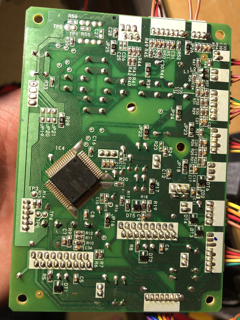
The microprocessor is, unfortunately, a custom marked device and I haven’t yet worked out which device it’s based on. A 10MHz ceramic oscillator provides the main clock for the chip, and it’s powered from a conventional 7805 linear voltage regulator.
Hacking
One very simple modification that can be made is to connect JP1, which was cut on my machine, to convert it from an 80 stitch machine to a 100 stitch machine. No further change – except to the stitch chart so you can tell what the stitches now are – is required!
My intention is to replace the control board in this machine with a 3D printer control board, which already provides for appropriate stepper drivers and control signal buffers. With the main motor control wired to the -ve side of a heater control pin, there’s no reason why a 3D printer board like a RAMPS (or, as I’m using, Makerbase SGEN-L) would need any modification to control this sewing machine. The biggest complication is the wiring of the steppers, where a track must be cut on the stepper connector PCBs to decouple the centre taps.
To help anyone else interested in doing such a project, I’ve mapped out the connectors on this machine, and a full table of connections is below. I’ve used the pin numbering marked on the board; be careful when using this, because the numbering runs in opposite directions on some connectors relative to others (because the inverted orientation is used on some to avoid misconnection during factory assembly).
Connectors
All of the connectors in use on the control board are around the periphery. The connector orientation and pitch is deliberately varied between so that no connector exactly matches any other – this ensures that during assembly (or reassembly!) you can’t really get it wrong.
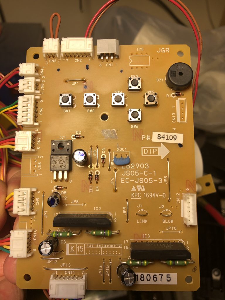
On the top of the board, there’s two stepper controllers, a 7805 regulator, a crystal oscillator, the buttons, a buzzer, and a handful of discrete components. On the underside there’s the microcontroller and a fair number of discrete transistors and passive components.
CN1 – LCD connector
The LCD on this machine appears to be an SPI device, or sufficiently similar to present signals that look like it. This is a zig-zag pinout on the board.
| 1 | 5V |
| 2 | Ground |
| 3 | Data (MOSI?) |
| 4 | Clock (seems to run at 200kHz normally) |
| 5 | 5V |
| 6 | CS |
CN2 – Reverse Switch
This is a 7 pin connector, but only 2 pins are used in the Brilliance 6180. The first two pins are connected to the reverse switch. The others appear to be wired appropriately for other buttons; perhaps another model has more inputs?
| 1 | Reverse switch (has 1K pullup on board) |
| 2 | Ground |
| 3 | |
| 4 | |
| 5 | Ground |
| 6 | |
| 7 |
CN3 – Speed control header
This is a 3-pin connector which is clearly intended to be connected to a slide potentiometer in other models. A simple wire jumper between the first two pins is present on the 6180; if you look at the Stylist 7258, a very similar model, you can see where there is a speed limiting control present instead.
| 1 | 5V |
| 2 | input signal |
| 3 | 0V |
CN4 – Winder Switch
There is a bobbin winder on this machine, and there is a switch to detect when it is engaged – presumably to stop the machine automatically when the bobbin is full. This is a simple switch input with a 10K pullup to 5V present on the board.
| 1 | Winder Switch (pulled up 10K to 5V) |
| 2 | Ground |
CN5 – Pedal input
This is a 2 pin connector with 5V and the pedal present. The pedal contains a 20Kohm variable resistor, and is configured so that it presents 20K when the pedal is up, and approximately 200 ohms when fully depressed.
| 1 | Pedal |
| 2 | 5V |
CN6 – Buttonhole switch
The Brilliance 6180 features an automatic button-hole device. This consists of a special foot, and a lever that mates with it and which extends down from the machine. This lever has two switches mounted on it. One detects when the lever is extended down to mate with the foot; the other detects whether the lever is in the neutral position or being pushed forwards or backwards. The control board interfaces with these switches in the normal way; all are connected with 10K pullups and short the input to ground.
| 1 | Ground |
| 2 | Ground |
| 3 | Switch input (closed when lever pushed towards user) |
| 4 | Switch input (closed when lever pushed away from user) |
| 5 | Lever up/down (open for up, closed for down) |
CN7 – Shaft sensors
The two slotted opto sensors on the main shaft are connected here. It’s important to note that the opto sensor LEDs are powered directly from the 20V input supply (via 620 ohm resistors on the sensor PCB) and not from the 5V logic supply. Note that it’s a 5 pin layout on the PCB, but only a 4 pin connector was present on the PCB (connected to pins 2-5).
| 1 | Not present on my machine |
| 2 | Rotation sensor (10K pullup to 5V) |
| 3 | Safe-to-move-needle sensor (10K pullup to 5V, open when unsafe) |
| 4 | Ground |
| 5 | 20V |
CN8 – Unknown
There’s a 3 pin header marked CN8 on the board, but on my machine no connector is present. There’s no obvious connection to the third pin here, and so it’s not clear what this could have been for. Perhaps as an LED power supply on a different model?
| 1 | Ground |
| 2 | 20V |
| 3 | N/C? |
CN9 – Power supply and speed control
CN9 is the main power input to the board, as well as providing connections to the speed control inputs on the PSU board. On the control board there’s a transistor between each of these inputs and ground. They appear to have a 12V pull-up on the PSU board.
| 1 | Motor relay (short to ground to enable motor) |
| 2 | Motor PWM (short to ground to power motor) |
| 3 | Ground |
| 4 | 20V |
CN10 – X-axis motor
CN10 is an 8-pin header on the board, but only a 5 pin connector is actually present on my machine. The pinout appears to be similar to CN11, the Y-axis motor, but the limit switch is not present and a smaller connector used as a result.
| 1 | Not present |
| 2 | Not present |
| 3 | Not present |
| 4 | Coil |
| 5 | Coil |
| 6 | Coil |
| 7 | Coil |
| 8 | Common centre tap |
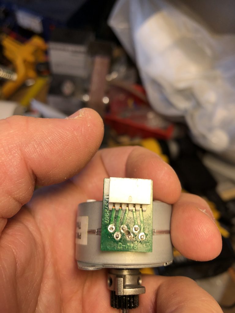
The motors used are actually 6-wire types, but the centre taps are connected together on the small header PCB that interfaces the motor to the cable leading back to the control PCB.
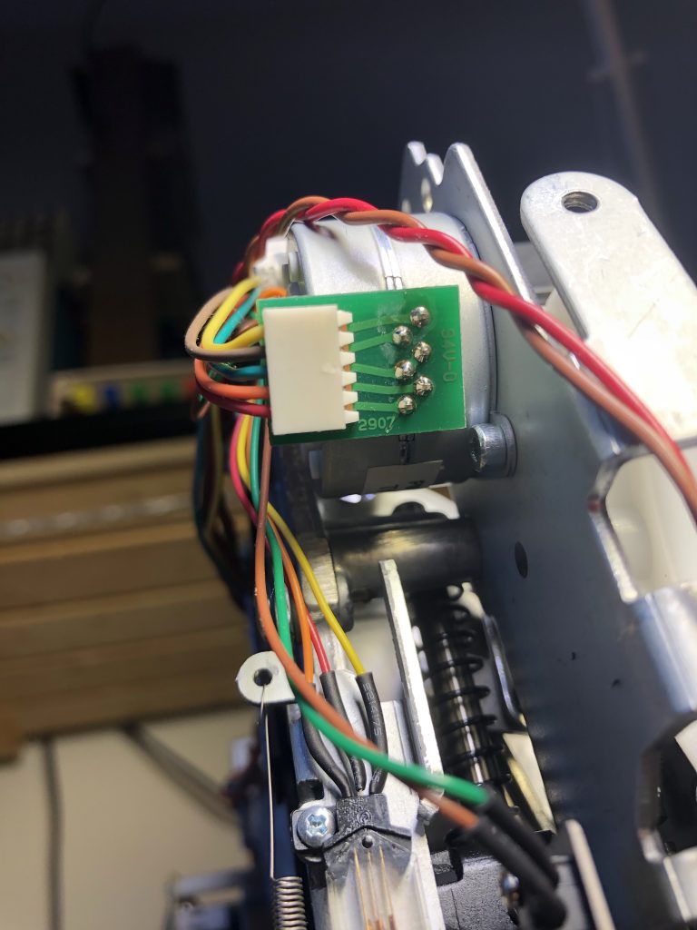
The motor used is a Minebea PM35L, which is a 7.5-degree-per-step motor, with a current rating of 500mA. Because it’s wired as unipolar motor, if you want to use it with standard 3D printer stepper controllers, you’ll need to modify the motor connector PCB. I found the easiest way to do this was by drilling out the track (which exists on both sides of the board!) linking the two centre-taps.
CN11 – Y-axis (feed dog control) motor
CN11 is connected to the feed dog control motor, and to the limit switch that controls the zeroing of this axis. This is a 7 pin connector.
| 1 | Ground |
| 2 | Limit switch (10K pullup to 5V on control board) |
| 3 | Coil |
| 4 | Coil |
| 5 | Coil |
| 6 | Coil |
| 7 | Common |
The Y-axis motor is identical to the X axis motor, and with the same modification required to use a normal bipolar driver.
CN12 – Unknown
CN12 is a vertical header, unlike the 90 degree headers used for everything else on the board. Its placement somewhat in from the edge suggests that this may be a programming connector, used only during production. It’s not clear what’s actually intended to be wired to this.
| 1 | Ground |
| 2 | Unknown |
| 3 | Unknown |
| 4 | Unknown (but has 10K to both ground and 5V) |
| 5 | Unknown (has 10K pullup to 5V) |
| 6 | 5V |
CN13 – Debug header
CN13 looks to be some sort of debug connector. It’s not populated on my board, and all of the pins connect to a set of also unpopulated resistor pads that would connect them to the microcontroller.
| 1 | N/C |
| 2 | Connects to JP21 |
| 3 | Connects to JP20 |
| 4 | Connects to JP19 |
Edit: One visitor asked me about the possibility of replacing the power supply fuse. Here’s a picture showing the location of the power supply board and the main fuse. Unfortunately it’s soldered in – I ended up replacing mine with another (somewhat inappropriate) fuse after popping it a few times by accident.